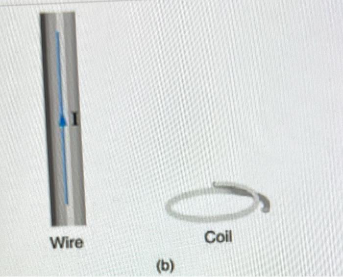
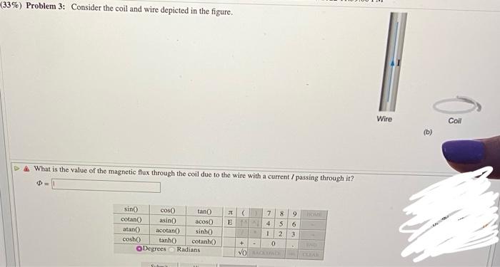
Consider the coil and wire depicted in the figure. This unassuming duo holds a wealth of physical and electrical properties that make them indispensable components in a wide range of applications. From motors and generators to transformers and solenoids, the coil and wire work in tandem to generate magnetic fields, transmit electrical energy, and convert power.
In this exploration, we delve into the characteristics, interactions, and practical uses of the coil and wire, unraveling their fundamental principles and showcasing their versatility in the realm of electrical engineering.
The coil, with its intricate windings, and the wire, with its conductive properties, form a symbiotic relationship that governs their behavior. The current flowing through the coil generates a magnetic field, which in turn exerts a force on the wire.
This force, influenced by factors such as current strength, coil geometry, and wire proximity, forms the basis of many electromagnetic devices.
Coil and Wire Characteristics
The coil and wire depicted in the figure consist of a cylindrical coil of wire with a specified number of turns, radius, and length. The wire used to construct the coil is characterized by its gauge (thickness) and material properties.
Coil Dimensions and Wire Properties
- The coil’s radius (r) and length (l) determine its physical size and shape.
- The wire’s gauge (g) indicates its thickness, with a lower gauge number representing a thicker wire.
- The wire’s length (L) is the total length of the wire used to create the coil.
Electrical Properties
- The coil’s resistance (R) is determined by the wire’s resistivity, length, and cross-sectional area.
- The coil’s inductance (L) is proportional to the number of turns squared and the coil’s radius.
- The capacitance (C) between the coil’s turns is typically negligible.
Coil and Wire Interactions

When an electric current flows through the coil, it generates a magnetic field. This magnetic field exerts a force on the wire, causing it to experience a deflection.
Magnetic Field and Force
- The magnetic field (B) is proportional to the current (I) and the number of turns (N) in the coil.
- The force (F) on the wire is proportional to the current, the magnetic field, and the length of the wire (l) within the field.
- The direction of the force is determined by the right-hand rule.
Applications of the Coil and Wire
The coil and wire are widely used in various applications, including:
Motors, Consider the coil and wire depicted in the figure
- Coils create a rotating magnetic field that interacts with a permanent magnet or another coil, producing torque and motion.
- The characteristics of the coil, such as the number of turns and the current, determine the motor’s speed and torque.
Generators
- Coils convert mechanical energy into electrical energy by rotating in a magnetic field.
- The coil’s properties influence the generator’s voltage and current output.
Transformers
- Coils in transformers transfer electrical energy from one circuit to another through electromagnetic induction.
- The ratio of turns in the primary and secondary coils determines the voltage transformation.
Design Considerations

When designing a device using a coil and wire, several key parameters must be considered:
Coil and Wire Properties
- The coil’s dimensions, wire gauge, and material determine its electrical and magnetic properties.
- The desired inductance, resistance, and force must be carefully calculated.
Performance Requirements
- The device’s functionality and efficiency depend on the coil and wire’s characteristics.
- Trade-offs between factors such as inductance, resistance, and size must be considered.
Simulation and Modeling: Consider The Coil And Wire Depicted In The Figure

Simulation and modeling tools can be used to predict the behavior of the coil and wire in a specific application:
Simulation Techniques
- Finite element analysis (FEA) and circuit simulation software can model the magnetic field and electrical properties.
- Simulations can optimize coil and wire design and predict device performance.
Limitations and Validation
- Simulations are approximations and should be validated with experimental data.
- Model accuracy depends on the quality of the input parameters and assumptions.
Answers to Common Questions
What is the relationship between the coil’s dimensions and the wire’s gauge and length?
The coil’s dimensions, particularly the number of turns and the coil’s diameter, influence the magnetic field strength. The wire’s gauge, or thickness, and length determine the resistance and inductance of the coil.
How does the magnetic field generated by the coil interact with the wire?
The magnetic field exerts a force on the wire, causing it to move or experience a torque. This force is proportional to the current flowing through the coil, the number of turns in the coil, and the distance between the coil and the wire.
What are some practical applications of the coil and wire?
Coils and wires are used in a wide range of applications, including motors, generators, transformers, solenoids, and inductors. They are essential components in power generation, transmission, and distribution systems, as well as in various electronic devices.